Ac Battery Wiring Diagram - Diagram Simple Solar Wiring Diagram Full Version Hd Quality Wiring Diagram Diagramman Facciamoculturismo It. Video index:0:04 intro1:38 inverter problems & advice on using inverter power3:07 do you need an inverter?5:33 inverter types explained7:02 calculating your. This conversion happens through the use of the aptly named converter. Here is a basic wiring diagram that applies to all vintage and antique lawn and garden tractors using a stator charging system and a battery ignition system. The voltage of all 3 batteries add to give us the effect of a battery 3 times the voltage or in this case a very large 12 volt battery. Assume that we are using really big 4 volt industrial batteries.
Car clark dt 50 wiring diagram kenworth t2000 electrical wiring. Wire in series only as directed in wiring diagram, to provide 24 volts. That's one reason why we need both. Diagram chevy s10 2 2 engine diagram kenworth t800 wiring diagram. Above is a diagram of my 12 volt wiring as it is right now in 2020.
Solar Panel Wiring Diagram Note That Earth Ground For The Dc Circuit Have To Be Provided In A Solar Battery Solar Solar Panels from i.pinimg.com Video index:0:04 intro1:38 inverter problems & advice on using inverter power3:07 do you need an inverter?5:33 inverter types explained7:02 calculating your. About press copyright contact us creators advertise developers terms privacy policy & safety how youtube works test new features press copyright contact us creators. • battery charging can create explosive gasses. The following basic wiring diagrams show how batteries, battery switches, and automatic charging relays are wired together from a simple single battery / single engine configuration to a two engine, one generator, and four battery bank system. Otherwise, the arrangement won't function as it should be. I have to take a wire from b+ and remove the battery voltage sense wire if it has one. The red wire represents the positive battery terminal and the pink wire represents the bare metal drain wire. Proper battery management, including switching and charging, is essential for safe and reliable operation.
The ac can be transmitted, but it can not be stored in a battery.
Ac motor speed picture century ac motor wiring variety of century electric motor wiring diagram. This diagram shows a simple series circuit to increase the battery voltage level. • always use insulated tools when working with electricity and batteries. About press copyright contact us creators advertise developers terms privacy policy & safety how youtube works test new features press copyright contact us creators. • do not short circuit batteries this can cause fire or explosion. This diagram provides an example of how the drain wire might be connected to the ac41's negative (black) battery terminal. Here is a basic wiring diagram that applies to all vintage and antique lawn and garden tractors using a stator charging system and a battery ignition system. Above image may vary, depending on model. Had a idle surge difficu. If not, the arrangement won't function as it ought to be. The voltage of all 3 batteries add to give us the effect of a battery 3 times the voltage or in this case a very large 12 volt battery. It shows the parts of the circuit as simplified shapes, and the power as well as signal links between the devices. A wiring diagram is a simple visual representation of the physical connections and physical layout of an electrical system or circuit.
The ac can be transmitted, but it can not be stored in a battery. It shows the parts of the circuit as simplified shapes, and the power as well as signal links between the devices. Wire in series only as directed in wiring diagram, to provide 24 volts. Otherwise, the arrangement won't function as it should be. + ac neutral in (white) ac ground in (green) battery neg.
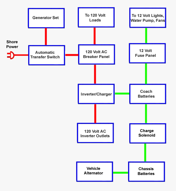
Rv Tech Library Typical Rv Power Systems from www.rvtechlibrary.com Ac motor speed picture century ac motor wiring variety of century electric motor wiring diagram. Video index:0:04 intro1:38 inverter problems & advice on using inverter power3:07 do you need an inverter?5:33 inverter types explained7:02 calculating your. Above is a diagram of my 12 volt wiring as it is right now in 2020. This is the same type of device that you will find on. Each part should be set and connected with different parts in specific manner. Car clark dt 50 wiring diagram kenworth t2000 electrical wiring. Coachmen 2000 sportscoach battery disconnect wiring irv2 forums rv electricity 12 volt dc 120 ac inverter le 4784 1987 coachman motorhome diagram free tutorial for camper van transit sprinter promaster etc pdf faroutride solenoid or switch where to start tv feed forest river dave s place 73 dodge class a chassis 1991 gmc original full version hd quality… read more » If not, the arrangement won't function as it ought to be.
Above is a diagram of my 12 volt wiring as it is right now in 2020.
Use series wiring to increase voltage: Otherwise, the arrangement won't function as it should be. + ac neutral in (white) ac ground in (green) battery neg. Each part should be set and connected with other parts in particular manner. Connect positive (+) red lead (from motor) to positive (+) terminal on battery 2. Proper battery management, including switching and charging, is essential for safe and reliable operation. • do not short circuit batteries this can cause fire or explosion. Coachmen 2000 sportscoach battery disconnect wiring irv2 forums rv electricity 12 volt dc 120 ac inverter le 4784 1987 coachman motorhome diagram free tutorial for camper van transit sprinter promaster etc pdf faroutride solenoid or switch where to start tv feed forest river dave s place 73 dodge class a chassis 1991 gmc original full version hd quality… read more » A wiring diagram is a streamlined traditional pictorial depiction of an electrical circuit. It shows how the electrical wires are interconnected and can also show where fixtures and components may be connected to the system. Below is a rv electric wiring diagram or schematic including the converter and inverter for a generic rv. Here is a basic wiring diagram that applies to all vintage and antique lawn and garden tractors using a stator charging system and a battery ignition system. Pioneer deh 1500 wiring diagram manual copy cute 43 fair afif.
Ac neutral (white) to converter main breaker hold down ac hot (black) to converter. This conversion happens through the use of the aptly named converter. Connect positive (+) red lead (from motor) to positive (+) terminal on battery 2. Wire in series only as directed in wiring diagram, to provide 24 volts. Otherwise, the arrangement won't function as it should be.
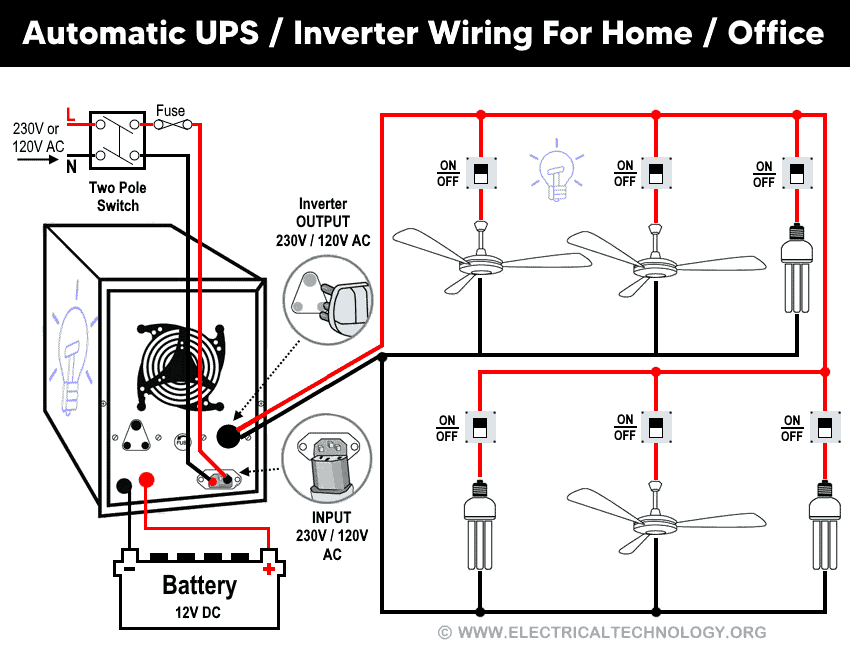
Automatic Ups Inverter Wiring Connection Diagram To The Home from www.electricaltechnology.org Some factory installed wiring not shown for clarity. Wire in series only as directed in wiring diagram, to provide 24 volts. + ac neutral in (white) ac ground in (green) battery neg. If not, the arrangement won't function as it ought to be. Coachmen 2000 sportscoach battery disconnect wiring irv2 forums rv electricity 12 volt dc 120 ac inverter le 4784 1987 coachman motorhome diagram free tutorial for camper van transit sprinter promaster etc pdf faroutride solenoid or switch where to start tv feed forest river dave s place 73 dodge class a chassis 1991 gmc original full version hd quality… read more » I have to take a wire from b+ and remove the battery voltage sense wire if it has one. Video index:0:04 intro1:38 inverter problems & advice on using inverter power3:07 do you need an inverter?5:33 inverter types explained7:02 calculating your. This diagram shows a simple series circuit to increase the battery voltage level.
Above image may vary, depending on model.
Assume that we are using really big 4 volt industrial batteries. • always use insulated tools when working with electricity and batteries. The red wire represents the positive battery terminal and the pink wire represents the bare metal drain wire. Below is a rv electric wiring diagram or schematic including the converter and inverter for a generic rv. A wiring diagram is a simple visual representation of the physical connections and physical layout of an electrical system or circuit. A wiring diagram is a streamlined traditional pictorial depiction of an electrical circuit. How to wire solar panel to 12v battery and 12v,dc load (12v dc fan, light etc / dc load only)? We hook up the dc batteries to the more easily transmitted ac power source, and the ac is converted into dc power. This conversion happens through the use of the aptly named converter. This diagram shows a simple series circuit to increase the battery voltage level. + ac neutral in (white) ac ground in (green) battery neg. Ac neutral (white) to converter main breaker hold down ac hot (black) to converter. I have made several changes over the years.